Magnetic loop 80 meter band.
- xtgaby
- May 30, 2020
- 1 min read
Updated: Mar 14, 2023
Calculated coil value of the loop is 6.4 uH as explained in de 40 meter band loop.
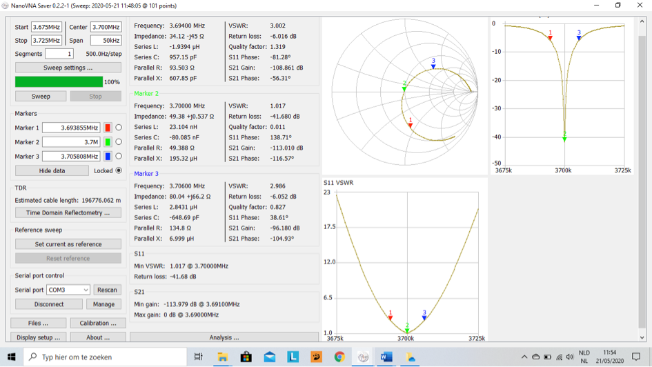
Target frequency = 3.700 KHz
Calculated value for the capacity = 290 pF.
I have used in this case RG58 with a capacitance of 100 pF / meter.
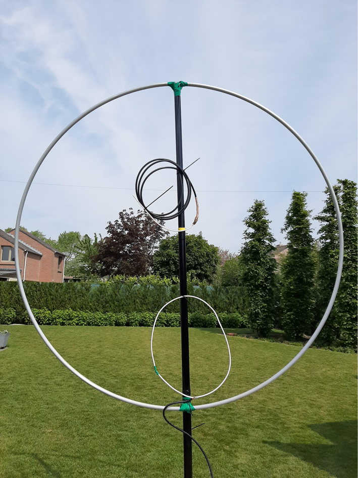
As you can see on this picture.
I had to change the small loop to insert the signal an ad 0,25 meter with the existing 1.30 meter for best SWR figures. Small loop becomes 1.55 meter.
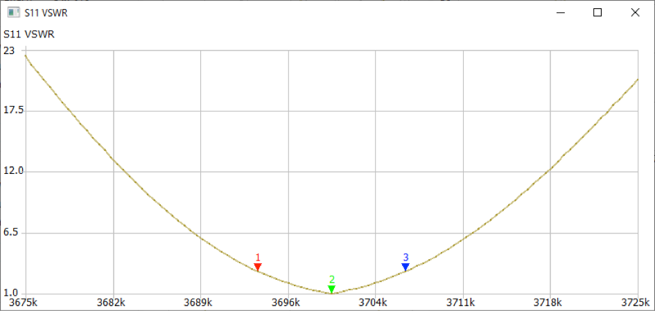
Marker 1 is SWR = 3 lower frequency,
Marker 2 is SWR =1,
Marker 3 is SWR = 3 higher frequency.
This means that we have an SWR =3 bandwith of 3.706 – 3.694 = 12 KHz.
SWR curve:
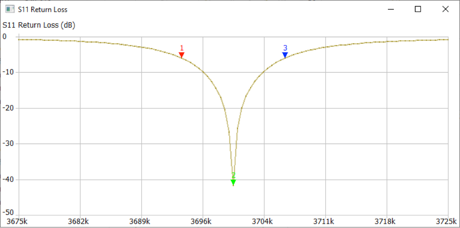
Return loss curve:
Comments